The New Frontier of Precision Manufacturing: How Flexible Automatic Assembly Equipment Breaks Through the Limits of Micro-Dimensional Assembly
Introduction
In precision fields such as watch movements, medical catheters, and MEMS sensors, assembly accuracy requirements have entered the “micron era” — the fit tolerance of watch gear shafts and holes ≤5μm (0.005mm), and the bonding offset of MEMS chips must be controlled within ±2μm. Traditional manual operations or rigid automated equipment can hardly meet such standards. Through the deep integration of vision technology, force control systems, and environmental control, flexible automatic assembly equipment is breaking through the precision limits of micro-dimensional assembly, making it possible for “millimeter-scale equipment to complete micron-scale operations.”
I. Core Technical Breakthroughs: A Precision Control Chain from “Visibility” to “Controllability”
The core challenges of micro-dimensional assembly lie in “insufficient visual resolution,” “difficulty in eliminating vibration interference,” and “crude contact force control.” Flexible equipment constructs a precision control closed loop through three major technology clusters.
1. Ultra-Precision Vision Guidance System: Micron-Level “Eyes”
Hardware Configuration:
- Adopting 12K resolution linear array cameras (such as Basler ace 2) with NA 0.95 telecentric lenses to achieve 1μm/pixel imaging accuracy, capable of clearly capturing the threads of 0.05mm diameter micro-screws;
- Integrating confocal sensors (such as Micro-Epsilon CFT6000) for Z-axis height measurement with an accuracy of ±0.1μm, solving the vertical deviation problem that traditional 2D vision cannot perceive.
Algorithm Innovation:
- Sub-pixel positioning algorithm based on deep learning (such as improved Hough transform) improves feature point positioning accuracy to 0.1 pixel (i.e., 0.1μm);
- Dynamic distortion compensation model: real-time collection of environmental temperature and lens temperature data, eliminating imaging 偏差 (deviations) caused by thermal expansion through polynomial fitting of over 200 parameters (errors in traditional equipment without compensation can reach 5μm).
2. Active Vibration Suppression Technology: Creating a “Zero-Vibration” Operation Space
Multi-Stage Vibration Isolation Architecture:
- Basic layer: air-floated vibration isolation platform (such as TMC Vibraplane), isolating 1-200Hz ground vibrations with residual vibration amplitude ≤1μm;
- Equipment layer: robotic arm joints integrated with piezoelectric ceramic actuators, which actively apply counterforces at a frequency of 10kHz through real-time feedback of vibration signals from acceleration sensors, suppressing inertial vibrations during robotic arm movement (end vibrations of traditional robotic arms can reach 20μm, reduced to ≤1μm after active control).
Case: The 0.01mm Miracle in a Swiss Watch Workshop
In the assembly of 1.2mm diameter watch gears, the vision system identifies tooth shape deviations at the 0.001mm level. Combined with an air-floated platform and active vibration control, the robotic arm completes shaft-hole insertion at a speed of 0.005mm/s. After 100,000 consecutive assemblies, the position deviation remains ≤0.01mm, and the yield rate increases from 75% in manual operation to 99.8%.
3. Force-Position Hybrid Control Technology: Micron-Level “Tactile” Sensing
Hardware-Software Collaboration:
- The end effector integrates a 1mN resolution micro-force sensor (such as ATI Nano17), capable of sensing minute force changes when the robotic arm contacts workpieces;
- Develop a “spring-damper” compliant control algorithm: when a contact force of 0.05N is detected, the robotic arm automatically switches to position-force hybrid control mode, fine-tuning the position with an accuracy of 0.1μm/step to avoid part damage caused by rigid collisions.
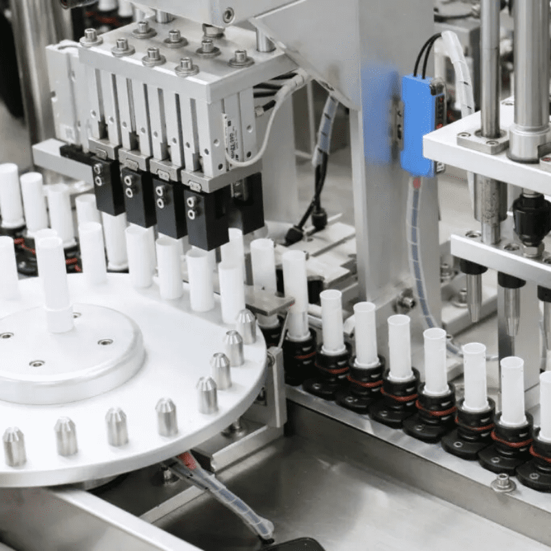
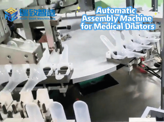
Typical Application: Multi-Layer Bonding of Medical Catheters
In the assembly of 0.5mm diameter vascular stent catheters, three layers of films with different materials (each 20μm thick) need to be precisely aligned and bonded. The flexible equipment real-time senses the bonding pressure (target value 0.2N±0.02N) through the force control system, combined with vision-guided angle compensation, resulting in a bonding offset ≤5μm. The yield rate increases from 60% with traditional equipment to 95%.
II. In-Depth Industry Applications: From “Impossible” to “Normalized” Precision Manufacturing
1. MEMS Sensors: The Automation Revolution in Chip-Level Assembly
Technical Pain Points: MEMS chips (such as accelerometers) measure only 1mm×1mm×0.5mm, requiring bonding with glass covers using gold-tin solder. The bonding pressure must be controlled at 5-10N, and temperature fluctuations ≤±1℃, which are almost impossible to achieve with traditional manual operations.
Flexible Solutions:
- Vision system: 3D structured light scanning (accuracy ±1μm) to obtain chip surface topography and automatically generate the optimal bonding path;
- Thermal control unit: integrated Peltier thermoelectric module, heating the bonding head from 25℃ to 300℃ within 100ms (accuracy ±0.5℃);
- Force control closed loop: real-time adjustment of pressure during bonding to ensure pressure deviation of each solder joint ≤0.5N.
Achievements: After introducing this equipment, a domestic MEMS manufacturer shortened the bonding time per chip from 8 minutes to 40 seconds, supported mixed production of over 20 models, increased capacity by 10 times, and reduced costs by 60%.
2. Precision Optical Devices: Micron-Level Optical Axis Alignment
Technical Requirements: In the assembly of mobile phone camera modules, the optical axis offset between the lens and image sensor (CIS) must be ≤5μm; otherwise, edge image quality will blur.
Innovations in Flexible Equipment:
- Laser collimator: emits 635nm parallel laser, detects optical axis offset through a dual-quadrant detector (PSD) with a resolution of 1μm;
- Six-axis micro-motion platform (accuracy ±0.5μm): supports six-degree-of-freedom adjustments for X/Y/Z axis translation and θx/θy/θz rotation. The robotic arm reads PSD data in real-time via Ethernet to close-loop adjust the lens position.
Test Data: After adopting this solution, a South Korean optical factory reduced the PPU (defects per unit) of module optical axis offset from 120 to 8, improved optical performance consistency by 92%, and supported rapid switching production of over 200 different lens specifications.
3. Microelectronics Packaging: The Bonding Miracle of Ultra-Fine Gold Wires
Technical Parameters: In LED chip packaging, 15μm diameter gold wires (three times thinner than human hair) need to be welded to pads with a solder joint diameter ≤30μm and tensile force ≥2gF.
Core Modules of Flexible Equipment:
- Ultrasonic welding head: 120kHz frequency, amplitude control accuracy ±0.1μm, ensuring gold wires are not broken during welding;
- Vision-force control collaboration: 3D vision measures pad warpage (accuracy ±2μm) before welding, and the force control system maintains a pressure of 1.5gF±0.1gF during welding to avoid pad damage from overpressure.
Industry Impact: After introduction by a Taiwan-funded packaging factory, the tensile qualification rate of gold wire welding increased from 85% to 99.1%, and the model switching time for different size chips was shortened from 4 hours to 30 minutes, successfully entering the high-end market of Mini LED packaging.
III. Challenges and Future: When Micron-Level Precision Meets Flexible Production
1. Current Technical Bottlenecks
- Incoming material consistency: The dimensional tolerance of micro-parts (such as ±5μm) is approaching the equipment’s positioning accuracy, making incoming material fluctuations the main error source. Upstream part processing accuracy needs to be improved.
- Environmental stability: The maintenance costs of cleanroom grades (requiring ISO 5 or above) and temperature-humidity control (23±0.5℃, 45%±5% humidity) are high, making them unaffordable for small and medium-sized enterprises.
- Algorithm robustness: Under extreme conditions (such as mirror reflection or transparent parts), the recognition rate of vision algorithms can drop from 99% to below 90%. Multi-modal sensing fusion technologies (such as vision + laser + capacitive sensing) need to be developed.
2. Future Technical Directions
- Nanometer-level assembly technology: Develop ultra-precision end effectors based on AFM (atomic force microscope) principles, aiming to achieve ±10nm positioning accuracy for semiconductor packaging and nanodevice manufacturing.
- Self-calibrating intelligent units: Integrate deep learning algorithms, allowing equipment to establish error compensation models for specific parts through 100 autonomous trials, eliminating the need for manual calibration.
- Digital twin-driven: Rehearse micro-assembly processes in the virtual space, and real-time correct equipment parameters through physical-digital mapping, expected to shorten first-piece debugging time by over 80%.
Conclusion
The breakthrough in micro-dimensional assembly is essentially a full-chain upgrade of “measurement accuracy → control accuracy → manufacturing accuracy.” Through the deep integration of vision, force control, and environmental control, flexible automatic assembly equipment has not only achieved the engineering miracle of “millimeter-scale equipment completing micron-scale operations” but also opened up new frontiers in precision manufacturing — from watches and medical devices to MEMS and semiconductors. When flexibility combines with precision, “artistic” assembly that could only be done manually is becoming an industrial standard scalable for replication. With continuous technological iteration, the “limits” of precision manufacturing will continue to be redefined, and flexible equipment will always be the core driving force to break through these limits.